RTD ACCURACY +/- °C PT100 Ω ALPHA 0.003850 to DIN 43760 IEC751 DIN EN 60 751
B GRADE
A GRADE
BAND 3 (1/3 DIN)
BAND 5 (1/10 DIN)
-200 °C
1.30 °C
0.55 °C
0.39 °C
0.38 °C
-150 °C
1.05 °C
0.45 °C
0.23 °C
0.21 °C
-100 °C
0.80 °C
0.35 °C
0.15 °C
0.12 °C
-90 °C
0.75 °C
0.33 °C
0.14 °C
0.10 °C
-80 °C
0.70 °C
0.31 °C
0.13 °C
0.09 °C
-70 °C
0.65 °C
0.29 °C
0.12 °C
0.08 °C
-60 °C
0.60 °C
0.27 °C
0.11 °C
0.07 °C
-50 °C
0.55 °C
0.25 °C
0.10 °C
0.06 °C
-40 °C
0.50 °C
0.23 °C
0.10 °C
0.06 °C
-30 °C
0.45 °C
0.21 °C
0.09 °C
0.05 °C
-20 °C
0.40 °C
0.19 °C
0.09 °C
0.04 °C
-10 °C
0.37 °C
0.17 °C
0.08 °C
0.03 °C
0 °C
0.30 °C
0.15 °C
0.08 °C
0.03 °C
10 °C
0.35 °C
0.17 °C
0.09 °C
0.04 °C
20 °C
0.40 °C
0.19 °C
0.10 °C
0.04 °C
30 °C
0.45 °C
0.21 °C
0.11 °C
0.05 °C
40 °C
0.50 °C
0.23 °C
0.12 °C
0.06 °C
50 °C
0.55 °C
0.25 °C
0.13 °C
0.07 °C
60 °C
0.60 °C
0.27 °C
0.14 °C
0.08 °C
70 °C
0.65 °C
0.29 °C
0.16 °C
0.09 °C
80 °C
0.70 °C
0.31 °C
0.17 °C
0.10 °C
90 °C
0.75 °C
0.33 °C
0.18 °C
0.11 °C
100 °C
0.80 °C
0.35 °C
0.19 °C
0.12 °C
110 °C
0.85 °C
0.37 °C
0.20 °C
0.13 °C
120 °C
0.90 °C
0.39 °C
0.21 °C
0.14 °C
130 °C
0.95 °C
0.41 °C
0.22 °C
0.15 °C
140 °C
1.00 °C
0.43 °C
0.24 °C
0.15 °C
150 °C
1.05 °C
0.45 °C
0.25 °C
0.16 °C
160 °C
1.10 °C
0.47 °C
0.26 °C
0.17 °C
170 °C
1.15 °C
0.49 °C
0.27 °C
0.18 °C
180 °C
1.20 °C
0.51 °C
0.29 °C
0.19 °C
190 °C
1.25 °C
0.53 °C
0.30 °C
0.21 °C
200 °C
1.30 °C
0.55 °C
0.31 °C
0.22 °C
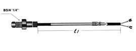
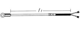
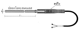
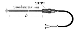
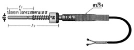
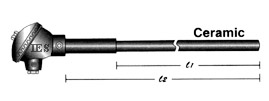
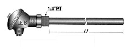
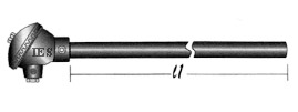
Resistance thermometer
Resistance thermometers, also called resistance temperature detectors (RTDs), are sensors used to measure temperature by correlating the resistance of the RTD element with temperature. Most RTD elements consist of a length of fine coiled wire wrapped around a ceramic or glass core. The element is usually quite fragile, so it is often placed inside a sheathed probe to protect it. The RTD element is made from a pure material whose resistance at various temperatures has been documented. The material has a predictable change in resistance as the temperature changes; it is this predictable change that is used to determine temperature.
R vs T relationship of various metals
Common RTD sensing elements constructed of platinum, copper or nickel have a unique, and repeatable and predictable resistance versus temperature relationship (R vs T) and operating temperature range. The R vs T relationship is defined as the amount of resistance change of the sensor per degree of temperature change.
Platinum is a noble metal and has the most stable resistance to temperature relationship over the largest temperature range. Nickel elements have a limited temperature range because the amount of change in resistance per degree of change in temperature becomes very non-linear at temperatures over 572 °F (300 °C). Copper has a very linear resistance to temperature relationship, however copper oxidizes at moderate temperatures and cannot be used over 302°F (150°C).
Platinum is the best metal for RTDs because it follows a very linear resistance to temperature relationship and it follows the R vs T relationship in a highly repeatable manner over a wide temperature range. The unique properties of platinum make it the material of choice for temperature standards over the range of -272.5 °C to 961.78 °C, and is used in the sensors that define the International Temperature Standard, ITS-90. It is made using platinum because of its linear resistance-temperature relationship and its chemical inertness.
The basic differentiator between metals used as resistive elements is the linear approximation of the R vs T relationship between 0 and 100 °C and is referred to as alpha, α. The equation below defines α, its units are ohm/ohm/°C.
the resistance of the sensor at 0°C
the resistance of the sensor at 100°C
Pure platinum has an alpha of 0.003925 ohm/ohm/°C and is used in the construction of laboratory grade RTDs. Conversely two widely recognized standards for industrial RTDs IEC 6075 and ASTM E-1137 specify an alpha of 0.00385 ohms/ohm/°C. Before these standards were widely adopted several different alpha values were used. It is still possible to find older probes that are made with platinum that have alpha values of 0.003916 ohms/ohm/°C and 0.003902 ohms/ohm/°C.
These different alpha values for platinum are achieved by doping; basically carefully introducing impurities into the platinum. The impurities introduced during doping become embedded in the lattice structure of the platinum and result in a different R vs.T curve and hence alpha value
Calibration
To characterize the R vs T relationship of any RTD over a temperature range that represents the planned range of use, calibration must be performed at temperatures other than 0°C and 100°C. Two common calibration methods are the fixed point method and the comparison method. [5]
Fixed point calibration, used for the highest accuracy calibrations, uses the triple point, freezing point or melting point of pure substances such as water, zinc, tin, and argon to generate a known and repeatable temperature. These cells allow the user to reproduce actual conditions of the ITS-90 temperature scale. Fixed point calibrations provide extremely accurate calibrations (within ±0.001°C) A common fixed point calibration method for industrial-grade probes is the ice bath. The equipment is inexpensive, easy to use, and can accommodate several sensors at once. The ice point is designated as a secondary standard because its accuracy is ±0.005°C (±0.009°F), compared to ±0.001°C (±0.0018°F) for primary fixed points.
Comparison calibrations, commonly used with secondary SPRTs and industrial RTDs, the thermometers being calibrated are compared to calibrated thermometers by means of a bath whose temperature is uniformly stable Unlike fixed point calibrations, comparisons can be made at any temperature between –100°C and 500°C (–148°F to 932°F). This method might be more cost-effective since several sensors can be calibrated simultaneously with automated equipment. These, electrically heated and well-stirred baths, use silicone oils and molten salts as the medium for the various calibration temperatures.
RTD Element Types
There are three main categories of RTD sensors; Thin Film, Wire-Wound, and Coiled Elements. While these types are the ones most widely used in industry there are some places where other more exotic shapes are used, for example carbon resistors are used at ultra low temperatures (-173 °C to -273 °C).
Carbon resistors Elements are widely available and are very inexpensive. They have very reproducible results at low temperatures. They are the most reliable form at extremely low temperatures. They generally do not suffer from significant hysteresis or strain gauge effects.
Strain Free Elements a wire coil minimally supported within a sealed housing filled with an inert gas. These sensors are used up to 961.78 °C and are used in the SPRT’s that define ITS-90. They consisted of platinum wire loosely coiled over a support structure so the element is free to expand and contract with temperature, but it is very susceptible to shock and vibration as the loops of platinum can sway back and forth causing deformation.
Thin Film Elements have a sensing element that is formed by depositing a very thin layer of resistive material, normal platinum, on a ceramic substrate; This layer is usually just 10 to 100 angstroms (1 to 10 nanometers) thick.[7] This film is then coated with an epoxy or glass that helps protect the deposited film and also acts as a strain relief for the external lead-wires. Disadvantages of this type are that they are not as stable as their wire wound or coiled counterparts. They also can only be used over a limited temperature range due to the different expansion rates of the substrate and resistive deposited giving a "strain gauge" effect that can be seen in the resistive temperature coefficient. These elements work with temperatures to 300 °C.
Wire-wound Elements can have greater accuracy, especially for wide temperature ranges. The coil diameter provides a compromise between mechanical stability and allowing expansion of the wire to minimize strain and consequential drift. The sensing wire is wrapped around an insulating mandrel or core. The winding core can be round or flat, but must be an electrical insulator. The coefficient of thermal expansion of the winding core material is matched to the sensing wire to minimize any mechanical strain. This strain on the element wire will result in a thermal measurement error. The sensing wire is connected to a larger wire, usually referred to as the element lead or wire. This wire is selected to be compatible with the sensing wire so that the combination does not generate an emf that would distort the thermal measurement. These elements work with temperatures to 660 °C.
Coiled elements have largely replaced wire-wound elements in industry. This design has a wire coil which can expand freely over temperature, held in place by some mechanical support which lets the coil keep its shape. This “strain free” design allows the sensing wire to expand and contract free of influence from other materials; in this respect it is similar to the SPRT, the primary standard upon which ITS-90 is based, while providing the durability necessary for industrial use. The basis of the sensing element is a small coil of platinum sensing wire. This coil resembles a filament in an incandescent light bulb. The housing or mandrel is a hard fired ceramic oxide tube with equally spaced bores that run transverse to the axes. The coil is inserted in the bores of the mandrel and then packed with a very finely ground ceramic powder. This permits the sensing wire to move while still remaining in good thermal contact with the process. These Elements works with temperatures to 850 °C.
The current international standard which specifies tolerance, and the temperature-to-electrical resistance relationship for platinum resistance thermometers is IEC 60751:2008, ASTM E1137 is also used in the United States. By far the most common devices used in industry have a nominal resistance of 100 ohms at 0 °C, and are called Pt100 sensors ('Pt' is the symbol for platinum). The sensitivity of a standard 100 ohm sensor is a nominal 0.00385 ohm/°C. RTDs with a sensitivity of 0.00375 and 0.00392 ohm/°C as well as a variety of others are also available.
As they are almost invariably made of platinum, they are often called platinum resistance thermometers (PRTs). They are slowly replacing the use of thermocouples in many industrial applications below 600 °C, due to higher accuracy and repeatability.Common RTD sensing elements constructed of platinum copper or nickel have a unique, and repeatable and predictable resistance versus temperature relationship (R vs T) and operating temperature range. The R vs T relationship is defined as the amount of resistance change of the sensor per degree of temperature change.
Wiring configurations
Two-wire configuration
The simplest resistance thermometer configuration uses two wires. It is only used when high accuracy is not required, as the resistance of the connecting wires is added to that of the sensor, leading to errors of measurement. This configuration allows use of 100 meters of cable. This applies equally to balanced bridge and fixed bridge system.
Three-wire configuration
In order to minimize the effects of the lead resistances, a three-wire configuration can be used. Using this method the two leads to the sensor are on adjoining arms. There is a lead resistance in each arm of the bridge so that the resistance is cancelled out, so long as the two lead resistances are accurately the same. This configuration allows up to 600 meters of cable.
Error on the schematic : A three wire RTD is connected in the following manner. One lead is connected to R1. That wire's lead resistance is measured as a part of the RTD resistance. One wire (of the two on the other end of the RTD) is connected to the lower end of R3. This wire's lead resistance is measured with R3, the reference resistor. One wire (of the two on the other end of the RTD) is connected to the supply return. (ground) This resistance is normally considered too low to matter in the measurement and is in series with the currents through the RTD and the reference resistor (R3) The lead resistance effects are all translated into common mode voltages that are rejected (common mode rejection) by the instrumentation amplifier. The wires are typically the same gauge and made of the same wire, to minimise temperature coefficient issues.
Four-wire configuration
The four-wire resistance thermometer configuration increases the accuracy and reliability of the resistance being measured: the resistance error due to lead wire resistance is zero. In the diagram above a standard two-terminal RTD is used with another pair of wires to form an additional loop that cancels out the lead resistance. The above Wheatstone bridge method uses a little more copper wire and is not a perfect solution. Below is a better configuration, four-wireKelvin connection. It provides full cancellation of spurious effects; cable resistance of up to 15 Ω can be handled.


 the resistance of the sensor at 0°C
 the resistance of the sensor at 100°C


