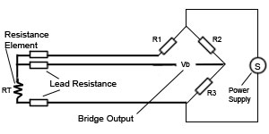
3 Wire RTD Sensor

3 Wire RTD Description
In order to minimize the effects of the lead resistances, a three-wire configuration can be used. Using this method the two leads to the sensor are on adjoining arms. There is a lead resistance in each arm of the bridge so that the resistance is cancelled out, so long as the two lead resistances are accurately the same.
3 Wire RTD Circuit

In a three-wire circuit two constant current sources are used, in order to compensate for the disadvantages described above for the two-wire circuits. Similar to the two-wire circuit the current source IK2 is used to measure the temperature dependent resistance RT including the lead and terminal contact resistances. The additional current source IK1 together with a third lead is used to separately compensate the lead and terminal contact resistances. Assuming the exact same lead and terminal contact resistances for all three leads, the effect on the accuracy of the temperature measurements can be eliminated. But practice has shown that it is not always possible to assure that the terminal contact resistances are always identical.